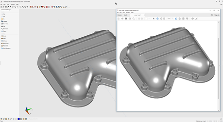
OneCNC CAD/CAM is known for powerful NC programming CAD/CAM solutions, but it also delivers a suite of shop-tested design tools including 3D surfacing and solids for mechanical part design.

OneCNC is very widely used CAD/CAM software worldwide and remains a program of popular choice among manufacturing engineers and CNC programmers. OneCNC Design is the CAD portion of our popular CAD CAM program, delivering easy CAD modelling tools with the most comprehensive CNC programming.

  • Imports industry standard file types such as STEP IGES, Parasolid, SAT, VDA-FS, Solidworks (.sldprt), Rhino, DWG and DXF, for easy communication with your customers.
  • Designed for the mechanical part design environment with functionality to construct in absolute or incremental wireframe surface or solid construction.
  • Does not include unwanted functionality not needed for mechanical design.
  • Does not need an investment in training time.

POWERFUL CAD CAM, MADE EASY. GET YOUR FREE CONSULTING AND QUOTE NOW

Get Started Now

Key Features

Design Freedom

OneCNC Solid Design is a computer-aided design solution that simplifies the creation of even the most complex parts with a powerful selection of CAD tools. OneCNC Solid Design is a standalone product but is also included in OneCNCXR8 CAM solutions. From fixing errors in imported models, to creating designs or work holding fixtures on a machine and so much more, this powerful CAD engine includes modelling and unique tools to get parts created in the shortest time.

Design Mechanical Parts

OneCNC Solid Design provides direct modelling with wireframe, surfaces or solids with file import functionality and preparation for CNC machining. A major advantage of OneCNC integrated CAD for CAM is the ability to import files from virtually any computer-aided design source. OneCNC Solid Design includes a large selection of CAD model translators as a standard feature, so no matter where a model was created, you can import and modify as needed for your machining purposes.

Image Tracing

OneCNC Solid Design makes it possible to work with files including PNG, JPG, TIFF, and raster-based images and create an automatic trace outline used for CAM such as engraving pocketing profiling or drilling operations. After tracing the wireframe tools can be used to prepare the trace outline for processing or further modelling. The image could be a corporate logo to be embossed onto a product by pocketing or profiling around the traced image.

Smart Plane

The smart plane system transforms solid modelling into a simple task. User can extrude bosses, create solid cuts, split by plane, model directly on faces and much more. Geometry creation can be constructed with the same plane control. The smart plane revolutionizes model and geometry construction allowing users to simply pick a face to work from and create further wireframe surface or model construction as the angles are automatically obtained for the new construction plane.

Wireframe

OneCNC Solid Design Includes everything you need for the creation and editing of lines, arcs, splines, and points. Beyond 2D sketch creation, 3D capabilities offer unlimited flexibility to create the geometry you need with ease. An important feature of these tools is the ability to construct move transform in both incremental or absolute while observing smart plane control. The wireframe can then be used base for the surface or model construction.

Surfaces

OneCNC Solid Design Surface modelling is an excellent way to create, edit, and display shapes from simple surfaces of revolution to complex organic shapes that cannot easily be done with wireframe. OneCNC gives you a powerful set of surface design tools for straightforward control over every detail of your work. The surfaces if fully enclosed can be then merged to form a solid for further solids editing such as shelling or filleting.

Solids

OneCNC Solid Design assists the designer to be sure that the part looks exactly as they want. It also gives additional ability to construct models from the simplest wireframe sketches and to continue to edit the model to meet your desired result. Solid modelling is the most complete because it simulates a complete part internally and externally. Solid models can be sectioned to reveal their internal features, and they can be checked for correct assembly and fit. OneCNC has the tools for this complete construction sectioning and dynamic display of the model. 

Drafting

OneCNC Solid Design drafting tools for dimensions, labels, and notes are part of our drafting functionality to communicate important design information to the shop floor. OneCNC provides the detailing tools required for mechanical design including tolerance and notation. Horizontal and vertical automatic alignment is easily controlled and positioned. Models can be automatically sectioned for intelligent automatic dimensioning by simple clicking of the user.

2D & 3D

OneCNC Solid Design provides a powerful time saving function for the user to create 2D layouts in paper space of a 3D model automatically. This can include 2D or 3D sectional views with full hidden line detail. The time saving of this can be enormous and provides an easy method of including details of quotations of manufactured parts. This can then be output as a PDF completed drawing that can be easily read on most computer devices.

Hybrid Modelling

OneCNC Solid Design hybrid modelling provides greater flexibility and lets you mix and match your modelling techniques. Need to add surface or wireframe elements to a solid that is a simple function.  Want to quickly add solid components to a complex surface model that is also very easy. OneCNC Solids ability gives you the speed of solids, the power of surfaces, and the simplicity of wireframe. You choose the right tool for the right job. OneCNC provides the tools to construct your part from any combination of these.

MBD Model Based Definition

For years, engineers used 2D drawings to deliver product manufacturing information even though they designed models in 3D. Using model-based definition (MBD) methods, engineers now embed product data directly in the 3D models, creating a single, reliable source of truth for the whole extended team. That not only makes sense, it prevents errors and saves everybody time. OneCNC Solid Design is working towards providing the tools you need to annotate, publish, and view MBD-compliant models.

File Collaboration

File compatibility is very important feature of manufacturing CNC parts. OneCNC Solid Design can Import, create, and manipulate wireframe, surfaces, and solids data in preparation for CNC. OneCNC Solid Design can read CAD files from CAD, DWG, DXF, IGES, Autodesk Inventor (using STEP), KeyCreator (using STEP), Parasolids, Rhino 3DM, SOLIDWORKS (SLDPRT, or STEP), SAT (ACIS solids), Solid Edge (using STEP), SpaceClaim Files (using STEP), STEP, STL, and VDA.

OneCNC Industry 4.0

OneCNC addresses the emerging shift in manufacturing towards Industry 4.0. This ensures users can merge into these goals and have the full benefits of digitalisation. Complete connectivity is provided by way of translators or direct file importation that handles the latest STEP IGES Parasolid SLDPRT SAT 3DM and VADFS to suit Solidworks, Inventor, Rhino3D, Ironcad, Spaceclaim and others. All of these digital processes are necessary to ensure connectivity that comes with Industry 4.0.